Electro-static “mini-panel”
I was intrigued a few months ago to learn about a new driver – the electro-static “mini panels” made by Involve Audio. I purchased my pair from Rob MacKinlay of ER Audio, who I understand was also involved in the design of the panels. Since I quite like the sound of panel speakers (in general), the driver – capable of covering from a few hundred Hz up to 20 kHz – offered some intriguing possibilities, from a high-end desktop system up to a mid/tweeter in a multi-way active system.
I’m currently experimenting with them in a 3-way active open baffle speaker. I’m finding that panels don’t follow the usual “rules.” I expected the panels to be quite directional – we are, after all, talking about a tweeter with a radiating area 140 x 380 mm in size. However, it’s more complicated than that.
Here is the simulated on-axis response of a radiator of that size on a 380 x 1200mm baffle, with the “microphone” at varying distances from the panel. The panel’s center is 900mm from the floor, and it is centered horizontally. The distances from the panel to the microphone are 0.5 m (green), 1 m (purple), 2 m (grey), and 4 m (red).
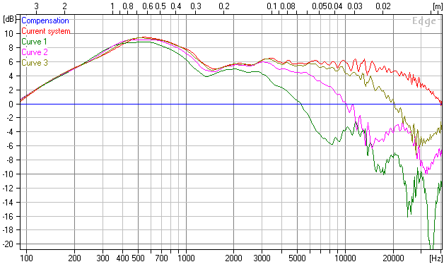
Minipanel simulated on-axis response at 0.5, 1, 2, and 4 m
Obviously, frequency response varies with distance, with the closer distances showing reduced output and some dips in the response at high frequencies. At 10 kHz, for example, the difference between the 1 and 2m distances is about 4 dB. Another thing to note on the simulation are some “wiggles” around 13-14 kHz. This is purely a matter of geometry – the simulation assumes the driver itself is “perfect”.
How does an actual measurement compare? Here is the actual panel on a 380 x 1200 mm baffle, measured at microphone distances of 0.5 m (red), 1 m (green), 2 m (blue), and 4 m (purple):
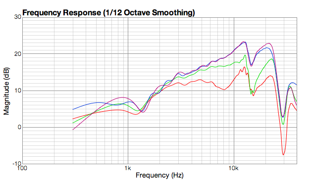
Minipanel measured on-axis at 0.5, 1, 2, and 4m
This measurement is gated at 2 ms, so has 500 Hz resolution. The plots were adjusted by 6 dB for each doubling of distance, to compensate for SPL drop-off, and to make clear how the overall shape of the response changes with distance. Basically, the response tilts up more as distance increases.
Compared to the simulation, the funny business around 13-14 kHz is more pronounced, and tends to show up (in this and other merasurements) as a distinct peak. But overall, and with the exception of the 4m plot, the response change for each doubling of distance is very similar in the measurement as it is in the simulation. (The 4m plot does move away from the 2m plot, but not as far as predicted by the simulation.) This is not a “fault” with the panel, but simply a consequence of its size (and dimensions).
This suggests that measurement and equalization needs to be done at the listening distance. The nominal 1 m distance will give incorrect results.
What about directionality? We would expect a tweeter that is over 6″ wide to be quite directional. Here are simulated plots at an assumed listening distance of 2.4 m, at horizontal angles of 0 (on-axis), 5 degrees, 10 degrees, and 15 degrees:
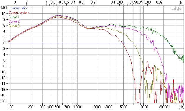
Mini-panel simulated response at horizontal angles of 0, 5, 10, 15 degrees
As expected, off-axis response at high frequencies falls very quickly. Note again that these responses are simply due to the panel width. Also, there is nothing that can be done to the size or shape of the baffle that will change them. In fact, if we put the panel in a box, we get pretty much the same responses (above 2 kHz), as shown in this simulation:
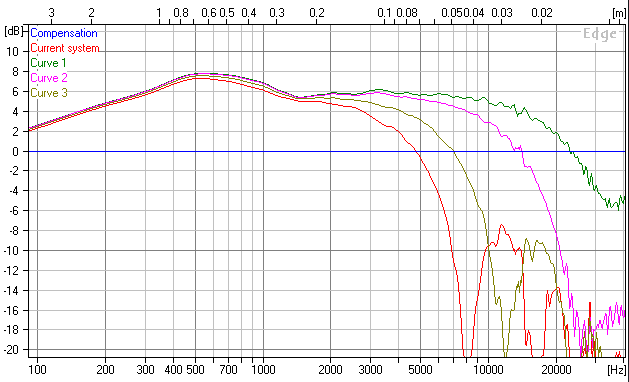
Mini-panel in box, simulated response at horizontal angles of 0, 5, 10, 15 degrees
What about actual measurements? Here they are (note: these are in-room measurements, gated at 3 ms, so some of the wiggles are due to reflections):
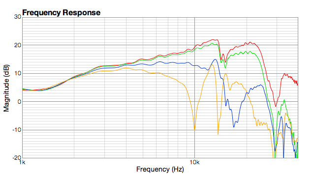
Mini-panel measured responses at horizontal angles of 0, 5, 10, 15 degrees
As before, the overall shape of the response tilts upwards compared to the simulation and the 13-14 kHz wiggles are more pronounced, but overall the differences between the responses follow the same pattern in the actual measurement as in the simulation. The response at 5 degrees doesn’t drop as fast, and the notches in the 10 and 15 degree responses are higher in frequency. These obervations suggest that the effective panel width is smaller than the physical measured width of 140 mm, and/or that the panel is not behaving as a flat piston.
Those notches, by the way, are due to lobing effects, and as the angle increases further you can see them move further down in frequency. This is, again, just the way that a large radiating surface behaves at frequencies for which its size is large relative to wavelength.
So, an interesting driver that poses some challenges for the DIYer in terms of optimizing its use. Currently, I’ve EQed my prototype 3-way for a listening distance of 2.4m with a horizontal offset of about ten degrees (speakers “intersecting” in front of me), and am enjoying listening to them. More in a future issue of the ‘Zine!
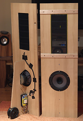
The response is somewhat similar to the BG neo10, although with a peak that is higher up in frequency.