How to make a 90 degree calibration file
Sometimes, a 90 degree microphone calibration file is useful. When measuring speakers in my home theater, for example, I find it a lot easier to just point the microphone at the ceiling with the 90 degree cal file loaded, than moving the microphone to point in the general direction of each speaker.
I verified in Appendix A of my article The miniDSP nanoAVR – a Case Study that, while there is a measurable difference between the two orientations (pointed at the speaker with the zero-degree calibration file, vs pointed at the ceiling with the 90-degree calibration file), it is small and unlikely to have any effect on equalization.
One of the advantages of purchasing a microphone from Cross-Spectrum Labs is that you get a 90 degree calibration file included. However, you may already have a good calibrated microphone and not particularly feel like buying another. (I understand!) So, this article contains instructions on how to make a 90-degree calibration file. Your prerequisite, of course, is that your microphone already has a 0-degree calibration file. You also need to be able to use Room EQ Wizard (REW).
Background
When you make a measurement with a calibrated microphone, you are not changing anything that the microphone does. All that happens is that the software alters the measured frequency response in accordance with the calibration file. The math, in fact, is simple:
- Actual response = Measured response – calibration file response
The actual response is the “real” frequency response at a point in space (the tip of the microphone capsule). The measured response is what the measurement program will measure at that point in space without using a cal file. And the calibration file response is the magnitude column in the cal file (we’ll see an example below).
Let’s simplify the names:
- A = M – C
and rearrange:
- C = M – A
In other words, to get the 90-degree calibration file response, we only need take the measured response with the mic at 90 degrees, then we subtract the actual response with the mic at 90 degrees. But hang on, aren’t we trying to pull ourselves up by our bootstraps? – the actual response is the reason we are trying to do this in the first place and we don’t have that yet!
The thing is, though, the actual response with the mic at 90 degrees (using the 90 degree cal file) is the same as the actual response with the mic at 0 degrees (using the 0 degree cal file). So we can get A by pointing the mic at the speaker and measuring it using the 0 degree cal file.
Clear as mud? Never mind, just follow the steps below carefully.
Steps
- Position the microphone pointed directly at a speaker and fairly close (to minimize room reflections). I used a small fullrange driver with the microphone positioned 20 cm away.
- Load the 0 degree calibration file and take a measurement. Rename it to A (actual response).
- Reposition the microphone so that it is pointed at 90 degrees. The tip of the mic must be in the same location as before.
- Clear the calibration file and take a measurement. Rename it to M (measured response). [Note: leave the microphone where it is, as you will need it again later.]
- Apply 1/3rd octave smoothing to both measurements.
- View A, and go to File -> Export -> Measurement as text, and save the file A.txt.
- Open A.txt in a text editor and locate the first line starting with a number greater than 1000. Delete everything before that line. Don’t leave a blank line at the start. Save A.txt.
- View M, and go to File -> Export -> Measurement as text, and save the file M.txt.
- Open M.txt and locate the first line starting with a number greater than 1000. Delete everything before that line. Don’t leave a blank line at the start. Save M.txt.
- Open a spreadsheet (I used Microsoft Excel but others should work fine).
- Position the cursor in cell A1 and import M.txt. Depending on the program the exact way you do this may vary, but you will typically use options that say it is a text file, with fields delimited by spaces or tabs. It should like a bit look this:

- Position the cursor in cell D1 and import A.txt. Now it should like a bit look this:

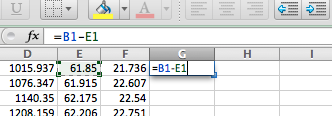
- In cell G1, enter the formula =B1-E1 :

- Select all the cells from G1 down to G55, or whichever is the last row with numbers in it. Press Ctrl-D or locate the Fill Down command. The formula gets pasted in each cell.
- Select all of Column G and do a Copy.
- Select Column H and do a Paste Special -> Values only. This copies the result of the equation, without copying the equation itself.
- In cell I1, enter the number 0.
- Use Fill Down to paste the 0 all the way to the last row with numbers (I55 in my case). The result should look like this:

- Select columns B through G and delete them. You should have three columns left, like this:

- Use Save As.. to save the spreadsheet as a tab-delimited text file, named C.txt.
- Make a copy of your calibration file, and name it something useful, like serial-90deg.txt.
- Open serial-90deg.txt in a text editor and locate the first line starting with a number greater than 1000. Delete that line and everything after it.
- Open C.txt, Select All and Copy its contents, then paste at the end of the open serial-90deg.txt file. Don’t leave a blank line. Save serial-90deg.txt.
- You now need to verify that the calibration file works as intended. Back in REW, load serial-90deg.txt as a cal file (Preferences->Mic/Meter).
- Run a measurement, and rename it to V.
- In the Overlays pane, compare A and V. They should be very close. (If not, something went wrong.)
- Optionally, you can use File -> Import Frequency Response to import serial-90deg.txt to see how it looks. (Set vertical limits to say +/- 10 dB.)
Example 1: CSL-calibrated Dayton EMM-6
I use the CSL-calibrated EMM-6 as my first example, because I already have a 90-degree cal file from Cross-Spectrum Labs for it. That way I can see how the cal file I came up with compares.
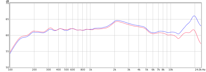
Here’s my A in blue and M in red (1/3rd octave smoothing):

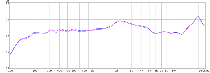
Here’s my A again in blue and V in purple:

Good!!
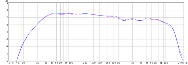
Here is the comparison of the 90-degree cal file from Cross-Spectrum Labs in blue with the cal file that I just generated in purple:

Example 2: miniDSP UMIK-1
I don’t have a 90-degree cal file for the miniDSP UMIK-1, so I will generate one and verify it as described in steps 24-27.
Here’s A in blue and M in red (1/3rd octave smoothing):

Here’s A in blue and V in purple:

Here, out of curiosity, is the miniDSP 0 degree cal file in red and the generated 90 degree cal file in purple:

Additional notes
The procedure given above seems long and complicated, but it’s one of those things that takes longer to describe than to actually do. I tried to find a simple way of doing it, but this is the best I’ve found using readily-available tools (and no coding).
- The procedure uses the existing data from the cal file below 1 kHz, and the new data above 1 khz. This is because the mic response due to orientation varies only at high frequencies. In addition, it’s hard (or impossible) to get repeatably accurate measurements at low frequencies because of ambient noise (traffic, planes, wind, footsteps, …)
- A full range driver is best to use, as it avoids any directionality effect that might occur if positioning the microphone in front of a speaker with multiple drivers. If you don’t have a full-range driver, try:
- Moving the switchover frequency up. You may get a bit of a glitch though.
- Moving the mic further away (e.g. 50cm instead of 20 cm). This may give a slightly less accurate result due to room reflections but will probably be just fine.
- I created column I for the phase data. However, most measurement programs will probably be fine without it.
- The two times I’ve done this so far, there is a small glitch at 1 khz in the cal file. This could be avoided by matching A and M exactly at 1 kHz prior to exporting. However, the glitch I got was only around 0.1 dB so I decided it wasn’t worth the effort.
- The impulse response of A and V does look a little different. I’m not sure at this point whether there’s ever a situation where this might matter.
Please let me know in comments below if you try this out and how you went. Thanks!
Postscript
You can, of course, come up with a method based on the above to calibrate one microphone based on another – but instead of rotating the mic 90 degrees, you measure using the second microphone. In order to get good low-frequency readings, the measurements should be done in two halves, as described here, and spliced together.
Hi John,
I just wanted to say thank you very much for this. I’ve just done this to create a 90 degrees calibration file for my Umik-1 from the standard calibration file, and it worked great.
There was no phase data in the original file, so I didn’t add it. It doesn’t look like REW needs it anyway.
Thanks again for taking the time to share this, most appreciated!
Hi Manni, sure, glad it helped. BTW there’s now a “generic” 90 degree calculator on the miniDSP UMIK-1 page, I’d be interested to know how that compares to the one you got using this method. WRT to phase data, good point, looks like REW doesn’t worry if it’s not there.
Hi John,
I did find the utility in the MiniDSP forum and I tried it.
The results were very similar to the results I got with your method, although they seem to correct a small variation between 2-5kHz. Overall, as it’s much easier and faster, I guess the utility is the way to go (I was surprised to see it worked so well). I’m really glad I had read your article first and made my own file, following your instructions to verify it. I’m not sure I’d have trusted a utility could do it automatically otherwise :).
Overall the main differences using both methods are above 10kHz, with a max of around 5dB around 15kHz (in my room). The two corrections are very, very similar, and the small differences probably not audible.
Thanks again for taking the time to post this!
Thx for sharing. I have a UMIK-1 on its way to my home, currently using a ECM999 that is not calibrated, so I will calibrate it against the UMIK-1 when it arrives.
Is this the utility you are talking about in MiniDSP forum?
http://www.minidsp.com/forum/umik-questions/10088-translate-0-degree-calibration-to-90-degree
If not, could you point me to the right utility, please?
Thanks!
Me again …
If you don’t have a full range driver and taking in consideration that A and M don’t really start to differ until 2.5KHz (at least with your UMIK unit), do you think that it could be possible to use as a source the tweeter of a loudspeaker with a crossover frequency of 2 KHz or lower?
Thx