A sample soundcard measurement – Edirol UA-25EX
This is an example of the measurement protocol described in A simple test protocol for USB/Firewire soundcards. I’m using this one as an example because I’m replacing it. Since I’m hoping to get a review out of the newer soundcards, I thought the older one would be a good example to use for this, as it also provides a reference to demonstrate how dramatically technology (for a given cost) has improved in a few short years.
The measurement programs that I am using are FuzzMeasure Pro and the Electroacoustics Toolbox. These are Mac programs but there are Windows equivalents.
1. Level calibration
Full-scale output on the UA-25EX is 4.6V RMS. The line input is the best option for performing loopback tests. 1.o V RMS is obtained with the output level set just past 12 o’clock.
To get line-level signals, use the TRS input of combo jack 2 and turn on the “Hi-Z” switch. Full-scale input is achieved with the gain control set a little before 12 o’clock.
2. Frequency response
I measured this unit at 48 kHz only.
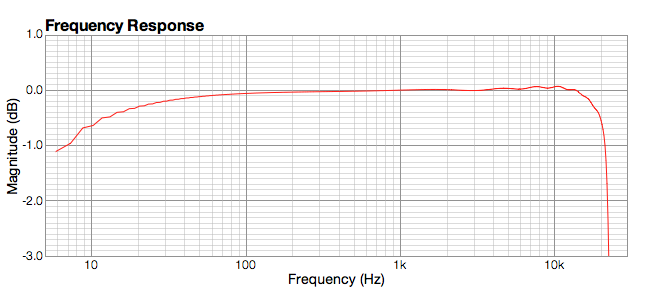
UA-25EX frequency response @ 48 kHz
It’s within a dB down from 10 Hz to 20 kHz.
3. Residual noise
The UA-25EX supports only 44.1 and 48 kHz. This is selected by a switch on the back. The noise level for 48 kHz for good enough, with no obvious spurious frequency-specific noise, so I left it set there.
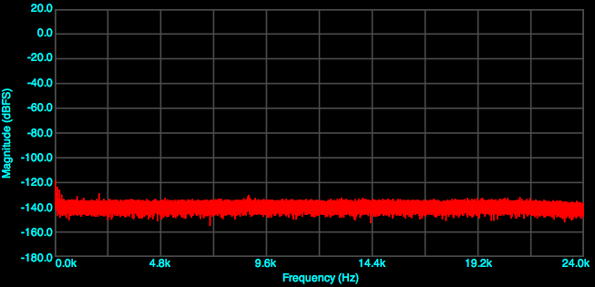
UA-25EX residual @48kHz
4. Harmonic distortion
Here are the distortion plots with 1 kHz input. At -1 dBV input:
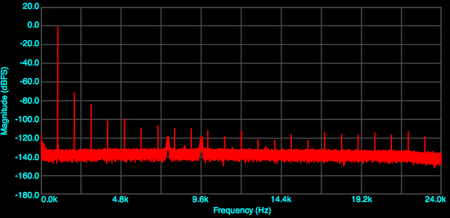
UA-25EX Harmonic Distortion, 48 kHz, -1 dBV
At -20 dBV input:
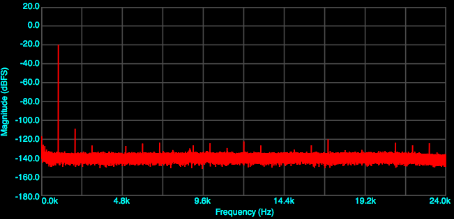
UA-25EX Harmonic Distortion, 48 kHz, -20 dBV
Note that the distortion level does drop dramatically when the signal level is dropped – a number of distortion components drop far faster than the signal level. At -1 dBV, THD calculates to -69.9 dB; at -20 dbV, THD calculates to -87.9 dBV. (That is relative to the fundamental.)
The -1 dBV measure is not particularly good for a modern line-level component. The -20 dBV case is not too bad. Neither are terrible, but neither compare very well to newer devices.
5. CCIF intermodulation distortion
Here are the plots at -1 dB:
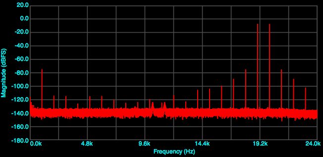
Edirol UA-25EX CCIF IMD, -1 dBV
At this signal level, neither the odd or even distortion component are lower then -80 dB. Here is the plot at -20 dB signal level:
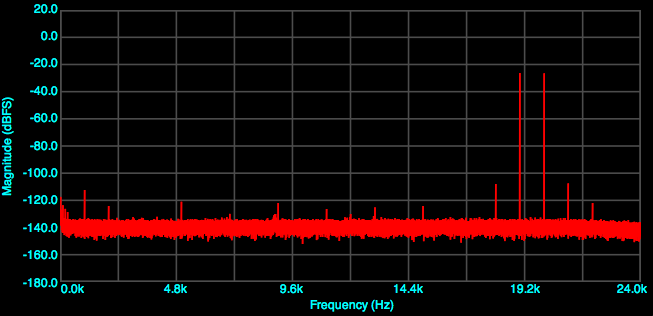
Edirol UA-25EX CCIF IMD, -20 dBV
This is better, with odd and even-order components (1 kHz and 18/20 kHz respectively) being around 90 dB down from the signal.
6. SMPTE intermodulation distortion
I’m pretty sure this test results is not represented properly in other tests that I’ve seen posted on the web. Anyway, here is what the UA-25EX does with -1 dBV (peak) signal level:
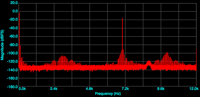
Edirol UA-25EX SMPTE IMD, -1 dBV
The sidebands of the 7 kHz component are 90 dB down relative to full-scale. Relative to the 7 kHz carrier, it’s more like -75 dB. Here is the result at a -20 dBV signal level:
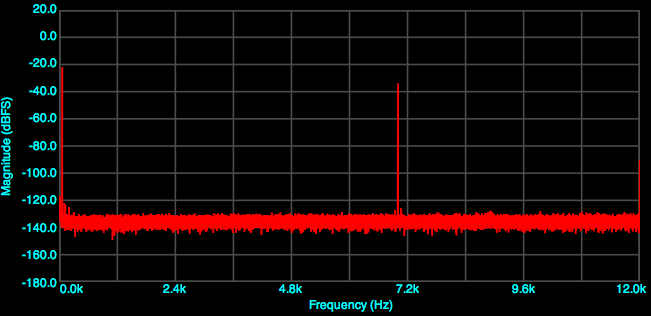
Edirol UA-25EX SMPTE IMD, -20 dBV
Most distortion components drop away rapidly with decreased signal level.
Concluding remarks
I felt that it would be helpful to record the objective performance of my “outgoing” audio interface. It helps to provide a reference for improvements that have been made in recent years, as well as to “prove out” the simple test protocol for USB/Firewire soundcards.
Looks like distortion caused by the wrong capacitor dielectric used in circuit around the opamps. Likely X7R dielectric when C0G/NPO should be used. Distortion in this case is proportional to the voltage across the capacitor and so it scales down rapidly when viewed on a log decibel graph (every -6dB is half voltage).
A bit of DIY could be very productive.